Piston Valve Applications (Full)
Piston actuated valves used in braking systems:
Piston valves can be used in braking systems used to check and fill braking systems for industrial vehicles.

The braking fluid is an oil with special properties capable to withstand high temperatures without boiling.


Piston actuated valves used in chillers:


Piston actuated valves used in automatic windscreen washing equipment:


Piston actuated valves used in kerosene filling rigs:

The equipment is used to fill thermic probes with kerosene. The system is made up of an injection unit, a cooling system, a vacuum pump, a pressure pump and a kerosene tank.
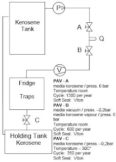
1st stage - vacuum
The probe is connected to the fast connection nozzle (Q). When the vacuum pump starts (V) valve (A) opens and creates a -0.2 bar depression inside the probe to prevent air bubbles from forming during filling operations.
2nd stage - Filling
Kerosene at room temperature contained in a tank is controlled by a pump (P) and sent to the filling unit. Valve (A) closes and valves (B) opens to let kerosene into the probe. When it is full, the tightness of the probe is tested up to 6 bar pressure.

Piston actuated valves used in high pressure casting systems:

The material used for manufacturing sanitary fittings is a slip, a very dense ceramic mixture made of clay and water.


Piston actuated valves used in industrial mixers in a vacuum:


By valve (E) connected to an external pump (P), the chamber is brought under pressure at 2 bar so that products can be ejected into commercial containers.
The valve that we would recommend for this application would be:

Piston valves can be used in braking systems used to check and fill braking systems for industrial vehicles.

The unit is installed in car manufacturing factories where braking system are tested before new cars are sold.
The unit carries out a dry cycle followed by a filling cycle. It automatically checks the system for even very small leakages and fills the fluid risk-free.

1st Stage – Test with vacuum
The unit is connected to the braking system. When the vacuum pump (V) is started, valve (A) opens and creates a –0,2 bar depression inside the empty circuit.
This stage is needed to dry test the braking system in case of leakages and prevent air bubbles from forming during filling operations.
This stage is needed to dry test the braking system in case of leakages and prevent air bubbles from forming during filling operations.
2nd Stage - Filling
Once testing has been completed, valve (A) closes, whereas valve B opens and controls the braking fluid at room temperature from the tank.
Pump (P) sends the fluid into the braking circuit at 2 bar pressure
Pump (P) sends the fluid into the braking circuit at 2 bar pressure
The valve that we would recommend for this application is:

Chillers are cooling units for water and other process fluids. Thermal energy is turned into freezing energy by an absorption freezing cycle, in which the coolant changes its state in combination with the substance used as an absorbent.
Thanks to their versatility, these units are widely used in the food industry: for cooling mineral water, juices, syrups, fermented wort, and water solutions of liquors; drinking water used in manufacturing pasta; water used in cooling rolling boards for candies, chocolate, icing and condensed milk.
In the mechanical and other industrial applications, chillers are used for cooling water in moulds, lubrication oils in tools, water in rollers in the paper industry.
In the mechanical and other industrial applications, chillers are used for cooling water in moulds, lubrication oils in tools, water in rollers in the paper industry.

Chillers are made up of a compressor, a condenser and an evaporator. The system consists of two hydraulic circuits, one for the coolant and one for water or for the process fluid to be cooled.
Cooling Circuit
The coolant coming from the evaporator is compressed and sent to the condenser by the compressor in the form of high-temperature gas.
By entering the condenser, the coolant turns into hot liquid, it is then controlled by the expansion valve and turns into cold gas. The gas goes into the evaporator and absorbs heat by getting in contact with process hot water. Then its cooling cycle starts again.
Process Fluid Circuit
Valve (A) controls process hot water and sends it to the evaporator, which works as a heat exchanger. When it gets in contact with the coolant, hot water yields its heat, cools and is then controlled by a valve (B) to be sent to its process again.
The type of valve that we would recommend for this application is:


The equipment is used to clean portholes during navigation.
In the past portholes were cleaned during the day by cleaners on moving trolleys. The hydraulic system was made up of pilot operated solenoid valves that sprayed water at 80 bar with dangers to passengers.
The solenoid valves were not perfectly synchronized and did not close at the same time, so at the end of every cycle water left inside the circuit mixed with rust and dripped on the portholes.
The solenoid valves were not perfectly synchronized and did not close at the same time, so at the end of every cycle water left inside the circuit mixed with rust and dripped on the portholes.
Nowadays both the logic and the hydraulic system have been revisited. The system is totally automatic, it is operated in the control room and cleaning is usually carried out at night to avoid dangers to passengers.
Pilot operated solenoid valves have been replaced by PAVs operated by direct acting solenoid valves.
The quality of water has been improved as well; it is now mixed with air at lower pressures. PAVs suitable for controlling water is equipped with travel switches to guarantee that they open simultaneously.
1st stage– Cleaning
Valve (A) controls water taken from a tank and pumped into the circuit by pomp (P) at the pressure of 4-5 bar.
Simultaneously valve (B) controls air from a compressor (C) at the pressure of 6 bar. Water mixed with air is sprayed on the portholes by a system of perforated pipes.
Pipes line the whole length of the ship and are perforated next to each porthole.
2nd stage – Drying
Once the cleaning stage is over, valve (A) closed so that only air enters the circuit.
Sprayed air dries the portholes and prevents water left inside the circuit from dripping
The valves that we recommend for this application are:

The equipment is used to fill thermic probes with kerosene. The system is made up of an injection unit, a cooling system, a vacuum pump, a pressure pump and a kerosene tank.

1st stage - vacuum
The probe is connected to the fast connection nozzle (Q). When the vacuum pump starts (V) valve (A) opens and creates a -0.2 bar depression inside the probe to prevent air bubbles from forming during filling operations.
2nd stage - Filling
Kerosene at room temperature contained in a tank is controlled by a pump (P) and sent to the filling unit. Valve (A) closes and valves (B) opens to let kerosene into the probe. When it is full, the tightness of the probe is tested up to 6 bar pressure.
3rd stage – Exhaust of the injection unit
When filling is over, the probe is disconnected from the injection unit, valve (B) closes, valve (A) reopens and the vacuum pump (V) starts, creating a depression inside the circuit. Kerosene left inside the unit is sucked up and sent into a heat exchanger to be cooled up to –30° and brought back to a liquid state. Valve (C) installed at the bottom of the heat exchanger opens at the end of the day and kerosene exhausts into a collecting tank. Kerosene is then carried back into the main tank.
The valve that we would recommend for this application is:


Industrial manufacturing of sanitary fittings such as rim bowls, wash basins, bidets or shower trays is carried out by high pressure casting systems.
These systems are completely automatic and can carry out all production stages without manual interventions.
The casting process consists of the following production stages:
- casting or feeding/exhausting of the slip;
- consolidation of the component and detachment from the mould;
- extraction of the component from the mould;
- washing of the mould.
The material used for manufacturing sanitary fittings is a slip, a very dense ceramic mixture made of clay and water.

During high-pressure casting, the slip is injected into a mould at 18 bar pressure through injection nozzles.
1) Consolidation of the component and detachment from the mould
When the casting cycle is over, valves control air at 7 bar pressure and inject it into the still closed mould in order to consolidate the component and detach it from the mould.
2) Extraction of the component from the mould
During the extraction, cycle valves control the vacuum cycle: thanks to suction generated by the injection nozzles in the mould, the component is retained until the robot picks it up and places it onto the drying bench.
3) Mould washing
Moulds are washed with water controlled by the valves at 10 bar pressure and injected into the inside circuits of the mould. The mould is made of micro-porous resin; thanks to its permeability it lets water filter outside thus eliminating all slip residues.
The type of valves that we would recommend for this type of application is:


The equipment is used to mix and homogenize liquid substances in manufacturing creams and other compounds in the pharmaceutical, cosmetic and food industries. Stages and mixing times depend on the manufacturers’ recipes.
The machine is made up of a control board, a mixing chamber, a shaking unit, a vacuum pump and a hydraulic circuit for warming up and cooling the mixing chamber.
The shaking unit consists of two slow shakers and a fast shaker (mixer) rotating in opposite directions to homogenize and prevent stagnation of highly viscous products or with a high specific gravity.

1st stage – Vacuum
By a vacuum pump (V), valve (A) creates a – 0,5 bar depression in the mixing chamber to prevent air from spoiling or deteriorating the quality of products during mixing operations.
2nd stage – Filling and Mixing
Liquid ingredients (ex. glycerine, water) are poured into the mixing chamber and the shaking unit starts rotating.
3rd stage – Warm-up
While mixing it might be necessary to warm up substances that do not melt at room temperature. The outside of the chamber is warmed up both by a valve (B), that controls steam up to 150°C from an external generator and by a valve (C), that controls hot water at 90-95°C and 3 bar pressure from an external boiler. The temperature inside the chamber is controlled by a thermic probe connected to the PLC, which operates the opening of the valves according to the requested temperature.
4th stage – Cooling
When products have been homogenized, the chamber is cooled externally by a valve (D), that controls cold water and glycol at –10° and 3 bar pressure, coming from an external chiller.
5th stage – Ejection
By valve (E) connected to an external pump (P), the chamber is brought under pressure at 2 bar so that products can be ejected into commercial containers.
The valve that we would recommend for this application would be:

Piston actuated valves used in manufacturing paraffin wax:


Extrusion machines and presses are used in the industrial production of candles.
These machines work with paraffin wax powder.
The equipment used for manufacturing paraffin wax powder consists of a leakage tank, a sprinkling unit and a pulverizing roller.

The leakage tank is loaded with solid paraffin wax, which is warmed up to the melting temperature by a coil heat exchanger.
Valve (A) controls diathermic oil at 140° at the pressure of 3 bar and lets it into the tank coil.
Liquefied paraffin is pumped into a warmed duct and sprinkled onto the cooling roller through special nozzles.
The sprinkling duct is warmed by diathermic oil controlled by a valve (B).
Cooled paraffin is scraped off the surface of the roller and collected in vibrating ducts.
The diameter of the cooling roller varies according to the quantity of paraffin to be obtained.
Paraffin wax powder is then loaded into the moulds where it is pressed into various shapes to get the finished candles.
The valve that we would recommend for this application is:

Piston actuated valves used in manufacturing plastic compounds:

The central part of the extruder consists of a cylinder with an endless screw turning inside.

Once the product is extruded, it is cut (6) and cooled to get its final shape.
The valve that we recommend for this application is:


Extrudes are used for blending plastic compounds or rubbers for industrial use.
The extrusion technology is widely used in processing plastic materials for manufacturing pipes, films, covering materials, cables, wires, sheathings, tapes, filaments, and structural shapes such as doors, windows and shutters.

The hopper (3) sends spherules of the polymer into the cylinder (2) to be warmed up to the melting point. By an electric motor (1) the endless screw heats and homogenizes the material, pushing it to the exhaust hole.
During the extrusion process dispensers (4)-(5) can mix thermoplastic additives, laden, reinforced or variously coloured materials.
Valves (7), connected to a cooling unit (8), control cold water at 10° C at the pressure of 2,5 bar to cool the cylinder in the various stages and ensure that the grinding temperature remains steady.
In the extrusion lines the exhaust hole has the same shape as the final product to be obtained; a flat section for films and laminated plastic, a circular section for pipes and more elaborate sections for structural shapes.
Once the product is extruded, it is cut (6) and cooled to get its final shape.
The valve that we recommend for this application is:

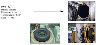
Piston actuated valves used in the curing of retreaded tyres:


In re-treaded tyres, the worn tread has been removed and replaced with new material of the same type as the original.
Old undamaged tyres are used as raw material.
Tires can be retread because the life of the framework is usually longer than the life of the tread.
The market of re-treaded tyres is growing steadily; their success is due to reliability, money saving, environmental protection. Re-treaded tyres are mainly used on planes and lorries; car owners may often choose this alternative too.


The re-treading process consists of an inspection of the framework to check its suitability to be re-treaded, a scraping of the remains of the worn tread, the laying of the new tread ring, the check of centering and balancing, and a final curing when the new tread becomes a whole with the framework.
During the cold process, the tread ring that is laid is pre-moulded and the curing is carried out in an autoclave. Valves (A) in the autoclave control steam at 140° at the pressure of 4 bar to warm up the chamber.
During the hot process, the tread ring is smooth and is moulded in the curing press.
There are two valves on the curing press: one (B) controls diathermic oil at 130° at the pressure of 2 bar for warming up the mould; the other (C) controls an air and steam mix at 90° at 3 bar used for inflation.
Temperatures and pressures are calculated for an optimal balance between the safety of the outcome and respect of the framework.
The type of valve we recommend for this applications is:

Piston actuated valves used in metal cleaning machines:

The solvent is kept clean by constant distillation.


Metal cleaning machines are industrial cleaning machines with a closed-circuit drying system.
They clean metallic parts of iron, aluminium, brass, bronze, stainless steel, etc. using solvents (ex. Perchloroethylene) and dry them with hot air.
The cleaning operation can be carried out in three stages:
a) with hot solvent;
b) with cold solvent;
c) with solvent fumes.
The three stages are independent and repeatable and their duration is adjustable according to the type of material to be de-greased.
The cycle ends with the complete drying of the material. The solvent is kept clean by constant distillation.

Components to be cleaned are placed inside a drum where the solvent circulates (hot, cold or fumes according to the selected cleaning cycle).
Dirt deposits on the bottom of the drum and is collected by a specially provided filter. The condensation and the fumes inside the drum are gathered and regenerated by a distiller after impurities (slag, air, water, oil, etc.) have been sorted out.
The clean solvent is then let into the cleaning cycle again. According to the cycle, the solvent can be warmed up by a steam jet at 140°C generated by a specially provided boiler and controlled by a valve (A).
It is then conveyed into the drum. For the drying operation, air is sucked up from the drum, depurated, warmed up and reintroduced into the drum.
The type of valve we recommend for this application is:

Piston actuated valves in autoclaves for food sterilization:
Piston actuated valves can be used in autoclave applications, in this specific application we are looking at the use of piston actuated valves in autoclaves for food sterilization.


Technical Information
V-Flow are the experts of flow control.
If you have a problem with flow control, we will find the solution.

Piston actuated valves can be used in autoclave applications, in this specific application we are looking at the use of piston actuated valves in autoclaves for food sterilization.
Autoclaves for sterilization are machines that process foodstuffs using steamy heat.
Food processing obtained through sterilization consists of:
- Steam cooking of food raw materials such as sauces, jams or marmalade;
- The packaging of fresh food into jars, bottles, cans or packets with superheated steam.
Through heat sterilization, all micro-organisms dangerous to human health are completely destroyed without toxic residues on foodstuff.

1st Stage - Vacuum
Product placed in a sterilizer is closed inside the autoclave. Before starting sterilization, valves (A)(B) create a –1 bar depression inside the chamber through a vacuum pump. Vacuum is needed to prevent air sacs at not controlled temperatures from creating, which are potentially dangerous to the quality of sterilization.
2nd Stage - Sterilization
During the sterilization cycle valve (C) controls steams at 121ºC temperature and 2 bar pressure for a processing time of 10-15 minutes.
3rd stage – Exhaust
Once the sterilization cycle is over, valve (C) closes, valve (D) opens restoring the atmospheric pressure, valves (E)(F) empty water created through steam condensation at 70°C temperature and atmospheric pressure. The port can then be opened to take out processed products.
The type of valve that we would recommend for this application is:

M&M Angle seat piston valves
M&M piston valves are highly recommended under these conditions:
M&M piston valves are manufactured in Italy, using the highest quality materials for a high-quality product.
M&M piston actuated valves use an external control media to pilot the actuator, where a piston valve is directly connected to the main seal that closes onto the main orifice, thereby controlling the flow of liquids and gases.
- Media containing dirt particles
- Highly viscous media (up to 600 cST (80°E); 1 centistoke = 1 mm2/s)
- High flow volumes
- High temperatures
- Damp environments or hazardous locations
 |  |
 |  |
Technical Information
The main seal material used in piston actuated valves:
A modified PTFE has been used as the main seal material since 2004 when it replaced the original PTFE material seal.
The modified PTFE seal provides these benefits over the previous version:
- Lower porosity and permeability
- Fewer void spaces
- Higher elasticity
- Reduced deformation under load
- Better chemical resistance to controlled media
- Smoother surface and improved design flexibility
The standard bonnet seals consist of 2 'V'-shaped FKM gaskets and a package of 25% graphite-filled PTFE gaskets.
High-temperature Piston actuated valves:
M&M can offer a piston valve that can be used up to 200°C, provided that the valve pressure limits are respected.
The main differences, in regards to the materials in this design, are as follows:
The main differences, in regards to the materials in this design, are as follows:
- Change of the actuator material: From standard PA6 to PA66 filled with 30% fibreglass
- All valves with DN > 25 with fixed plug design (to withstand turbulence caused by steam at high speed)
- Special design of bonnet chevrons, all are made of 25% graphite-filled PTFE
10 Reasons to use a piston actuated valve:
----------------------------------------------------------------------------------------------------------------------------------------------
Piston actuated valves can be found here, on our website:
http://v-flowsolutions.co.uk/actuated-valves/pneumatic/piston-valves/
http://v-flowsolutions.co.uk/actuated-valves/pneumatic/piston-valves/
----------------------------------------------------------------------------------------------------------------------------------------------
If you think V-Flow can help you then please contact us:
If you think V-Flow can help you then please contact us:
Telephone: +44 (0)1234 855888
Email: sales@v-flowsolutions.co.uk
Fax: +44 (0)1234 857775
V-Flow are the experts of flow control.
If you have a problem with flow control, we will find the solution.


Comments
Post a Comment